
The datasheet for this 16-position, 1.00 mm pitch FFC/FPC ZIF-style connector defines the absolute electrical limits designers must respect. Point: the part’s published limits (example: 0.5 A per contact and 50 V AC/DC) set the safe envelope. Evidence: the official datasheet lists voltage, current, contact resistance and test conditions. Explanation: translate those values into system-level margins and test plans before BOM freeze.
Purpose: convert raw datasheet numbers into practical guidance for power budgeting, thermal planning, and verification. Point: designers need clear checklists and test procedures. Evidence: datasheet sections (electrical, mechanical, reliability) map directly to design decisions. Explanation: this article highlights which datasheet entries matter, how to derate, and what bench and in-system tests to run for robust designs.
Part overview & how to read the 52271-1679 datasheet (background introduction)
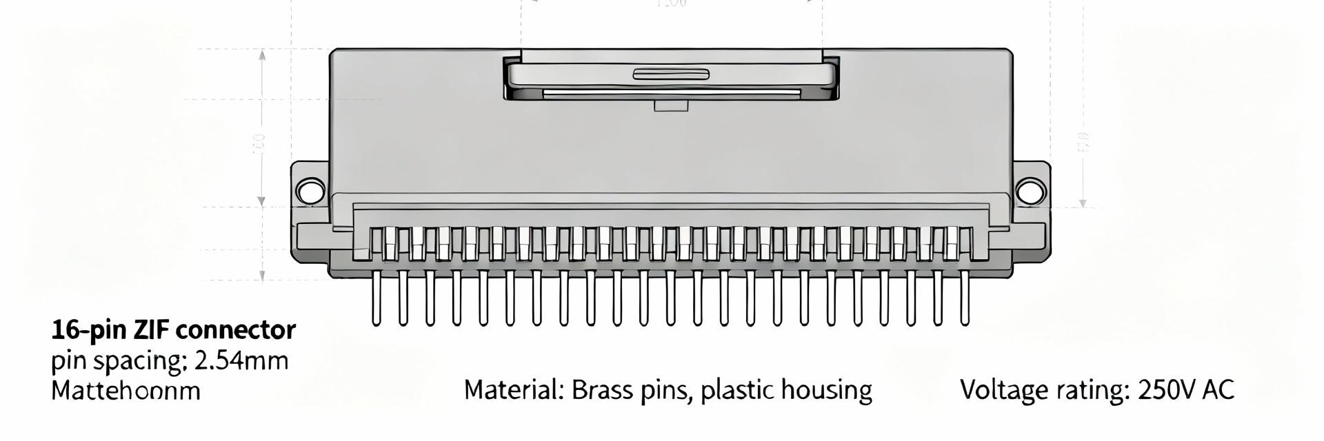
Point: begin by confirming the connector’s physical and identifier fields on the datasheet. Evidence: form factor and pin/pitch appear in the title block and dimensional tables. Explanation: capturing part number, pitch, pin count, mating orientation, and packaging code avoids cross-reference errors during procurement and layout handoff.
Form factor, pin count and key identifiers
Point: this part is a bottom-entry FFC/FPC ZIF (SMT receptacle) with 16 positions and 1.00 mm pitch. Evidence: the datasheet’s mechanical drawings and ordering code specify orientation, actuator type and reel/tray packaging. Explanation: verify footprint, row count, and actuator clearances against your PCB stackup and chassis openings before finalizing layout.
How the datasheet structure maps to design decisions
Point: read electrical ratings first, then mechanical and reliability sections. Evidence: electrical ratings determine power budget; mechanical dimensions determine PCB footprint; reliability covers lifecycle. Explanation: map: electrical ratings → power/voltage headroom; contact resistance & current rating → voltage drop/heat; mating cycles → maintenance and MTBF planning.
52271-1679 electrical specifications: ratings, limits and interpretations (data analysis)
Point: extract static ratings (max current, voltage, contact resistance, insulation) and use them directly for margining. Evidence: typical datasheet values include 0.5 A per contact and 50 V AC/DC maximum and list contact resistance and dielectric withstanding voltage under test conditions. Explanation: treat “maximum” as an absolute limit; design for lower operating values to allow margin for wear and temperature.
Static electrical ratings: voltage, current, contact resistance, insulation
Point: tabulate critical electrical specs for clear reference. Evidence: the table below is the suggested format to capture datasheet entries and design implications. Explanation: use this table early in the component KPI sheet and BOM notes so electrical and mechanical teams share the same assumptions.
| Spec | Datasheet Value | Test Condition | Design Implication |
|---|---|---|---|
| Max current per contact |
0.5 A
|
Specified temp, no airflow | Limit single-contact loads; parallelize or use alternate connector if >0.5 A |
| Max voltage | 50 V AC/DC | Insulation testing per datasheet | Maintain creepage/clearance and consider transient margins |
| Contact resistance | Typical/Max (see datasheet) | 4-wire measurement | Use R to compute I²R losses and voltage drop |
| Insulation resistance | Per datasheet | Specified voltage | Critical for high-impedance signals and leakage budgeting |
Thermal behavior & derating: power dissipation, temperature rise, and ambient limits
Point: use I²R to compute per-contact power loss and estimate temperature rise. Evidence: take the contact resistance from the datasheet and apply 0.5 A in I²R. Explanation: example calculation: with R_contact = 100 mΩ (illustrative), P = I²R = 0.25 × 0.1 = 0.025 W; small but cumulative in dense arrays—derate at elevated ambient and in stacked boards by applying conservative factors (e.g., reduce allowable current by 20–40% in constrained airflow).
Mechanical & environmental ratings that affect electrical performance (data analysis / method)
Point: mechanical specs and lifecycle metrics directly affect long-term electrical behavior. Evidence: datasheet lists insertion/removal force, actuator type and rated mating cycles. Explanation: increased contact resistance over life due to wear and contamination increases voltage drop; budget initial headroom for end-of-life resistance growth.
Mechanical dimensions, mating force, and lifecycle
Point: capture actuator type, pitch, insertion force and rated cycles from the mechanical section. Evidence: datasheet tables and drawings provide these numbers and recommended PCB footprint. Explanation: if your product expects heavy field cycles, choose connectors with higher rated mating cycles or include maintenance intervals in the service plan.
Environmental limits
Point: environmental stress degrades insulation and contact reliability. Evidence: operating/storage temperature ranges and referenced test standards appear in the qualification section. Explanation: for harsh environments, require humidity soak plus contact resistance checks and ensure material flammability and plating specs meet the application’s needs.
Test procedures and verification for 52271-1679 electrical performance (method / practical guide)
Point: perform bench tests that mirror datasheet test conditions to validate parts from a vendor. Evidence: recommended tests include 4-wire contact resistance, insulation resistance, dielectric strength, and current-loading thermal-rise tests per datasheet voltages/currents. Explanation: define sample size, pre-conditioning, and pass/fail thresholds tied to datasheet maxima with safety margins (e.g., 20% margin on max current).
Recommended bench tests
Point: step-by-step verification improves confidence in production components. Evidence: a 4-wire DC resistance test, dielectric ramp to rated voltage, and a thermal soak at expected current are standard. Explanation: document measurement temperature, sample conditioning, and require suppliers to provide test reports or allow incoming QA verification on a sample lot.
In-system validation
Point: validate performance under real loads and accelerated stress. Evidence: in-system checks include measuring voltage drop at max expected current and thermal monitoring during worst-case duty. Explanation: run thermal cycling, humidity exposure and current soak tests while logging contact resistance; define acceptance like ΔR_contact below a specified threshold and no arcing at rated voltage.
Selection, compliance and specification checklist for designers (action recommendations / case-oriented)
Strategic Overview: Use a compact pre-spec checklist to avoid costly rework. Evidence: checklist items should include current/voltage margins, pitch/footprint match, mating cycle, solder profile and operating temperature. Explanation: if required current >0.5 A, select alternate connector or parallel paths; if voltage >50 V, specify a higher-voltage-rated connector.
Quick selection checklist
- Confirm electrical, mechanical and thermal compatibility before adding to BOM.
- Cross-check datasheet current/voltage vs. actual requirements.
- Flag high-risk items early (e.g., heavy current on single contact).
Compliance & Procurement
- Verify RoHS/REACH and material flammability codes.
- Reference the official datasheet revision and check for part aliases.
- Confirm tape-and-reel orientation for SMT pick-and-place.
Frequently Asked Questions
What are the critical electrical specs to read in the datasheet for 52271-1679? +
Read maximum current per contact, maximum voltage, contact resistance (typical and max), insulation resistance, and dielectric withstanding voltage. These values, together with the specified test conditions, determine safe operating limits, required derating, and what bench tests to run during incoming inspection.
How should I derate the 0.5 A per-contact rating in high-temperature environments? +
Derate conservatively: reduce allowable current by 20–40% in elevated ambient or confined airflow conditions. Perform an I²R-based temperature-rise test using the datasheet contact resistance, log steady-state temperatures, and ensure the connector remains below material temperature limits under worst-case duty cycles.
Which bench tests best verify the electrical specs in the datasheet? +
Recommended tests: 4-wire contact resistance, insulation resistance at specified voltage for the given dwell time, dielectric strength with proper ramp, and current-load thermal-soak test. Define sample size, preconditioning, and pass/fail thresholds tied to datasheet maxima with a safety margin.








